


This series of products is a full digital bus type high-grade numerical controller with modular and open architecture based on NCUC industrial communication technology. This product has a 10.4” LED display. It supports all kinds of CNC communication servo motors and servo drives, including Absolute ones. It supports external I/O modules, handwheel, CF card, USB, Ethernet and electronic disk storage program, etc. HNC-818BM is mainly used in milling machines.
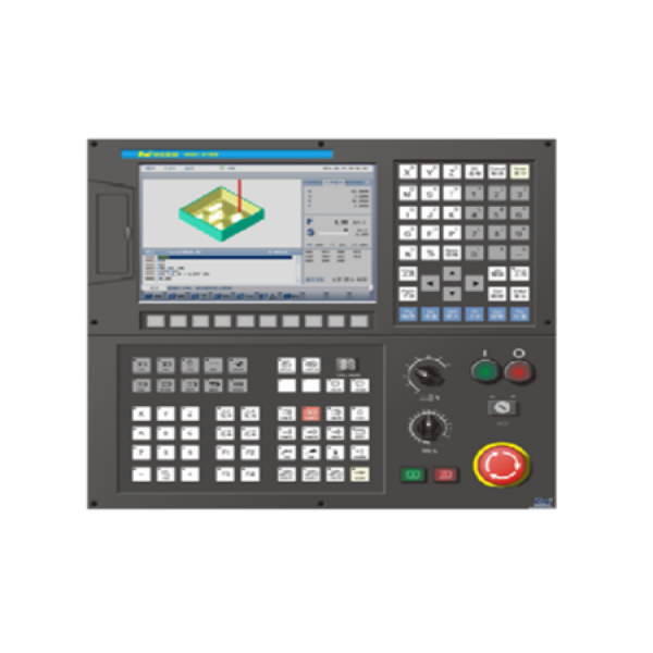
- True color graphic interface design, adapted 10.4" color LED display, 800*800 resolution, fault diagnosis and alarm, graphical display and simulation of the processing part, simple operation, is a CNC that is easy to master and use.
- Multi-axis multi-channel, supporting a maximum of 9 feeds/channel.
- You can choose various digital AC servo drive unit and spindle motor (synchronous, asynchronous, linear, torque motor).
- You can watch or edit the ladder diagram while the CNC is running. You can store block diagrams (interface is optional, graphics will not be lost).
- Supports handwheel interface.
- It supports the functions of Ganrty shaft synchronization, dynamic shaft release/catch and channel synchronization.
- The interpolation cycle is 4ms~0.5ms, and the minimum input unit is 10-4mm/degree/inch.
- It has a powerful macro and a further improved program from the HNC-21 series.
- Simplified programming: Mirroring, zooming, rotating, direct drawing size programming, etc.
- Supports processing point save/recovery function, reverse blanking and single, two-way step error compensation function.
- It communicates with the CNC tool through internal RS232 communication. It supports high-speed Ethernet data exchange.
- It stores 1MB program with CF card. It can be extended up to 2GB maximum, supports USB hot plug.
- It has 512MB of RAM and can process custom G-code.
- It is compatible with international standard G code programming and various popular CAD/CAM automatic programming systems. It also supports plan editing and draft programming (optional).
- Supports straight line interpolation, arc interpolation, polar coordinate interpolation, interpolation, cylinder spiral interpolation, etc. to support rotation, scaling, mirroring, fixed cycle, gear cutting, cutting tool compensation, user macro program, soft limit, etc.
- Supports gantry shaft synchronization, dynamic shaft release/catch, and channel synchronization.
- Continuous machining function and especially suitable for machining complex mold parts of CAD/CAM design.
- When the communication type PLC I/O unit is used, the maximum input/output support is 2048. The maximum distance between communication equipment can be up to 50 meters.
- Fully functional
| CNC Functions | Maximum controllable axes: 9 axes and 2 spindles
Maximum coordinate axes: 6 axes |
| Minimum interpolation cycle: 0.5ms minimum resolution: 10-4mm/deg/inch | |
| Maximum travel speed: 999,999 m/min (related to drive unit and machine tool) | |
| Line, arc, tooth, NURBS interpolation function Return to reference point | |
| Automatic acceleration and deceleration control (line/S curve) frame setting | |
| MDI Function M, S, T function machining process graphic simulation and real-time monitoring | |
| Internal secondary electronic gear constant milling cycle | |
| Maximum forward segment of small segment: 2048 segment processing speed: 7200 segments/second | |
| CNC Programming
Function |
Minimum programming unit: 10-4 mm/degree/inch
Maximum programming size: 999999.999 mm (minimum programming unit is 10-3) |
| Maximum programming lines: 2 billion
Metric system/English system programming |
|
| Absolute/incremental Programming
Macro instruction programming |
|
| Calling a subroutine
Setting workpiece coordinates |
|
| Selects coordinates to rotate, scale, and mirror the plane | |
| Interpolation
Function |
Line interpolation maximum 9 axes |
| Circular interpolation
Cutting by touch |
|
| Tool Compensation
Function |
Tool length compensation
Tool radius compensation RTCP |
| Operation Function | 10.4' LED color screen anti-static film programming panel and machine tool operation panel Anti-static electricity program and machine operation panel |
| Standard PC keyboard interface
Handwheel units (optional) |
|
| Graphic display and dynamic real-time simulation
Network communication (optional) |
|
| Feed axis function | Unconstrained axis rotation function
Maximum speed: 999999.999 mm/min |
| Feed rate override: 0% to 120%
Fast movement speed override: 0% to 100% |
|
| Maximum tracking error setting
Maximum positioning error setting |
|
| Various modes of returning to the reference point: one-way and two-way | |
| Spindle Function | Spindle speed: determined by PLC programming
Maximum speed: 999999.999 rpm |
| Spindle speed override: 0% to 150%
Display spindle speed and override |
|
| Variation rate and variation rate level: determined by PLC programming. | |
| Tapping function: Spindle-oriented tapping | |
| PLC Function | Built-in PLC Ladder diagram online monitoring and Nearby selection tool |
| Standard milling machine Ladder program
Online/offline programming and debugging |
|
| Additional Functions | The Spindle FWD/REW ATC Cooling Start/Stop |
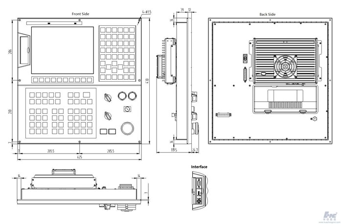
DIMENSIONS
![]() Serial 8 PLC programming-2017.2.21
Serial 8 PLC programming-2017.2.21
![]() HNC-818 User Manual (Programming)
HNC-818 User Manual (Programming)